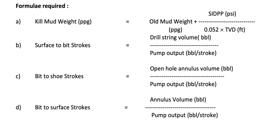
A kicks in drilling can be defined as a well control problem in which the pressure found within the drilled rock is greater than the mud hydrostatic pressure acting on the borehole . When this occurs, the greater formation pressure has a tendency to force formation fluids into the well bore. This fluid flow is called a kick. If the flow is successfully controlled, the kick has been killed. A blow out is the result of an uncontrolled kick.
The main principle involved in all well killing methods is to keep bottom hole pressure constant. The various kill methods are as follows:
a) Driller’s Method
b) Wait and Weight Method
c) Concurrent Method
d) Volumetric Method
In the first three methods the influx is circulated out and the heavy mud is pumped in the well keeping the bottom hole pressure constant. The fourth method i.e. Volumetric method is a non-circulating method in which the influx is brought out & heavy mud is placed in the well bore without circulation.
The Drillers method of killing may be preferred when sufficient barites or weighing materials are not readily available and MAASP is not critical. As this method can be started immediately, it has an advantage in case of salt water kicks as sand settling around BHA is minimum and in cases where gas migration may create problems.
Wait and Weight method of killing has advantage of lower annulus pressures and can be used when casing shoe strength is weak and MAASP is critical. The maximum shoe pressure will be lower if kill weight fluid starts up the annulus before the top of the influx is displaced to the shoe. If sufficient weighing materials are available at the site, the well can be killed in one circulation thereby saving time. Concurrent method is used when mud density cannot be increased to kill weight during the initial circulation, at least two complete circulations are required.
BRINGING THE PUMP TO KILL SPEED ON SURFACE / JACK UP RIG
It is important to understand the startup procedure, irrespective of kill method, for bringing the pump up to kill speed .
Pump should be brought to kill speed patiently. During this period if the casing pressure is allowed to increase it can cause formation breakdown or if the casing pressure is allowed to decrease it can cause entry of more influx into wellbore. To prevent this, following procedure is suggested.
a) Bring the pump to kill speed holding casing pressure constant by manipulating choke. Record drill pipe pressure as the correct initial circulating pressure (ICP). Compare it to the pre calculated ICP value.
b) When the pump is at the desired kill speed follow the pressure schedule according to the kill method being used.
Note : While bringing the pump to kill speed keeping casing pressure constant , there might be slight reduction in bottom hole pressure due to expansion of gas but this is compensated by the annular pressure losses.
If actual ICP is greater than the calculated ICP, use the actual ICP and correct same on the kill sheet. If the actual ICP is less than the calculated ICP, stop the pumps, close in the well and determine if a problem exists in the circulating system. Then retry bringing the pump on line.

- Formula sheet can be download from iwcf
Driller’s method the killing of a well is accomplished in two circulations
- In first circulation the influx is removed from the well bore using original mud density.
* In second circulation the kill mud replaces the original mud and restores the primary control of the well.
A. Killing Procedure( Drillers Method )
In this method the well is killed in two circulations.
* First Circulation
- a) Bring the pump up to kill speed in steps of 5 SPM, gradually opening the choke holding
casing pressure constant. - b) When the pump is up to kill speed, maintain drill pipe pressure constant .
- c) Circulate out the influx from the well maintaining drill pipe pressure constant.
- d) When the influx is out, stop the pump reducing the pump speed in steps of 5 SPM ,
gradually closing the choke, maintaining casing pressure constant. Record pressure, SIDPP and SICP should be equal to original SIDPP.
Note : In case recorded SIDPP & SICP are equal but more than original SIDPP value, it indicates trapped pressure in wellbore. Whereas if SICP is more than original SIDPP, it indicates that some influx is still in the wellbore.

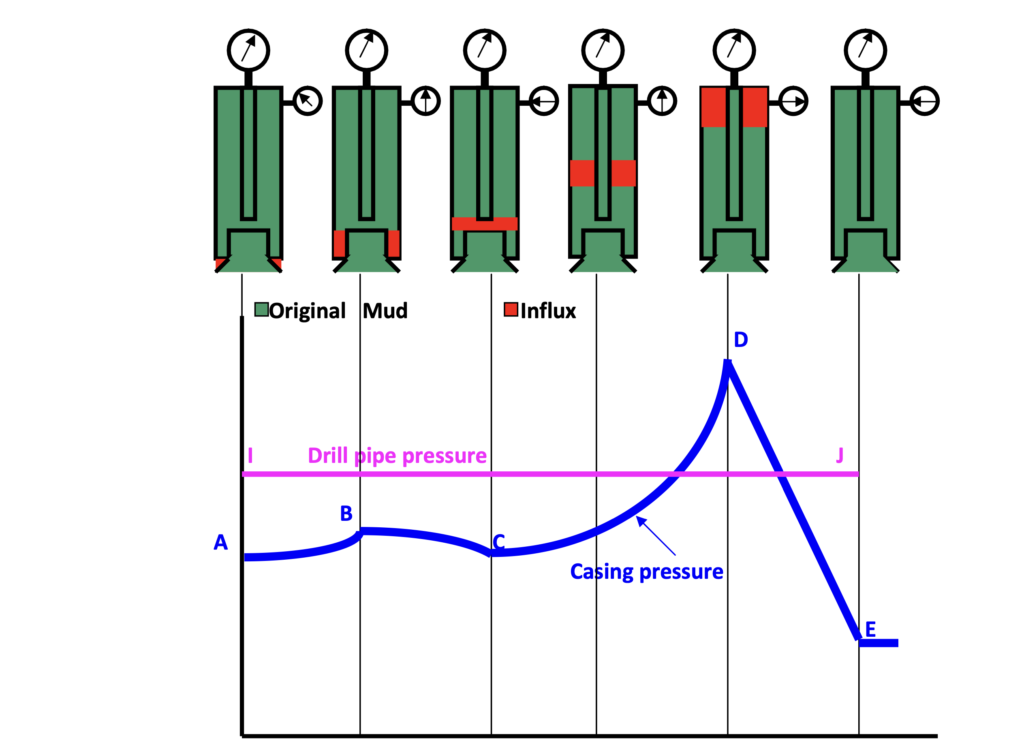
Pressure Profile of 1st cycle of Drillers Method
* Second Circulation
- a) Line up suction with kill mud.
- b) Bring the pump up to kill speed in steps of 5 SPM, gradually opening the choke, holding
casing pressure constant. - c) When the pump is at kill speed, pump kill mud from surface to bit, maintaining casing pressure constant.
- d) Pump kill mud from bit to surface, maintaining drill pipe pressure constant equal to
FCP. - e) When the kill mud reaches surface, stop the pump reducing the pump in steps of 5 SPM ,
gradually closing the choke maintaining casing pressure constant. Record pressures, SIDPP and SICP both should be equal to zero.
Open & observe the well. Add trip margin before resuming normal operation .
Casing Pressure Graph
A-B : Casing pressure rises as influx expands in drill collar annulus.
B-C : Casing pressure decreases as influx crosses over from drill collar annulus to drill pipe annulus & losses height.
C-D : Casing pressure again rises as influx now expands in drill pipe annulus and it becomes maximum when influx reaches surface at point ‘D’ on the graph.
D-E : Casing pressure reduces sharply as influx is removed from the wellbore.

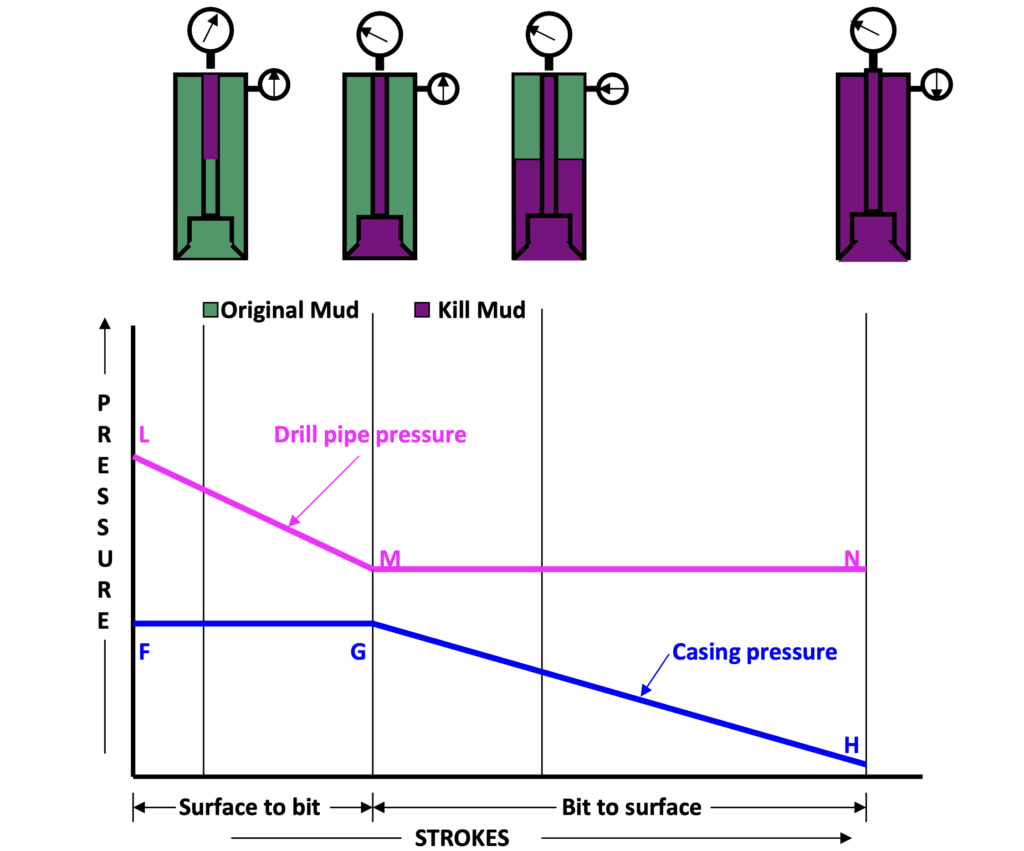
Pressure Profile 2nd cycle of Drillers Method
Drill Pipe Pressure Graph
I-J : Drill pipe pressure is held constant till the influx is removed from the wellbore.
Casing Pressure Graph
F-G : Casing pressure is held constant till kill mud is pumped from surface to bit.
G-H: Casing pressure reduces to zero as kill mud is pumped from bit to surface.
Drill Pipe Graph
L-M : Drill pipe pressure reduces as kill mud is pumped from surface to bit. During this period SIDPP drops & becomes zero whereas KRP increases to FCP value. On the whole drill pipe pressure reduces from ICP to FCP.
M-N : Drill pipe pressure is held constant as the kill mud is pumped from bit to surface.
B. WAIT AND WEIGHT METHOD
- In Wait and Weight method well is killed in one circulation using kill mud.
- In this method operations are delayed (wait) once the well is shut in, while a sufficient volume of kill (weight) mud has been prepared. As the kill mud is pumped to the bit the hydrostatic pressure in the Drill Pipe increases, this causes the drill pipe pressure to fall. At the same time, influx which is on its way up the annulus expands continuously and gains volume / height, thereby causing the hydrostatic pressure in annulus to fall and casing pressure to rise. Because of this , for maintaining BHP constant a calculated step down plan
for the drill pipe pressure must be used while pumping the kill mud from surface to the bit .
Killing Procedure ( Wait and Weight Method )
- Line up suction with kill mud.
b) Bring the pump up to kill speed in steps of 5 SPM, gradually opening the choke, holding
casing pressure constant.
c) When the pump is at kill speed, pump kill mud from surface to bit, maintaining drill pipe
pressure as per step down schedule( during this step drill pipe pressure will fall from ICP
to FCP ).
d) Pump kill mud from bit to surface, maintaining drill pipe pressure constant equal to
FCP.
e) When the kill mud reaches surface, stop the pump reducing the pump speed in steps of 5 SPM , gradually closing the choke maintaining casing pressure constant. Record pressures, SIDPP and SICP both should be equal to zero. Open & observe the well. Add trip margin before resuming normal operation .

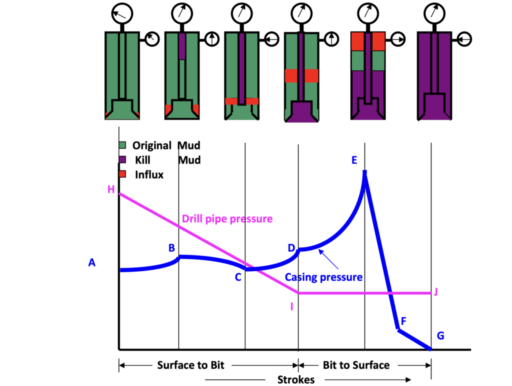
PRESSURE PROFILE- WAIT & WEIGHT METHOD
Casing Pressure Graph
A-B Casing pressure rises as influx expands in drill collar annulus.
B-C Casing pressure decreases as influx crosses over from drill collar annulus to drill pipe annulus & losses height.
C-D Casing pressure again rises as influx now expands in drill pipe annulus.
D-E Casing pressure continues to increase but initially at a slower rate as at this stage kill mud starts entering the annulus, later on casing pressure increases at a faster due to rapid expansion of gas.
E-F Casing pressure reduces sharply as influx is removed from the wellbore.
F-G Casing pressure further reduces as original mud is replaced by kill mud. Drill Pipe Pressure Graph
H-I Drill pipe reduces from ICP to FCP as kill mud is pumped from surface to bit.
I-J Drill pipe pressure is held constant at FCP as kill mud is pumped from bit to surface.
VOLUMETRIC METHOD OF WELL CONTROL
The volumetric method is a non-circulating killing method used for removing gas influx when there is little or no drill pipe in the hole, a wash out in the string or when the hole cannot be circulated. It works equally well for a situation where the well is closed-in and waiting on orders or equipment or for stripping in or out of hole. In this method the influx is brought up to the surface by means of migration & controlled expansion.
This process involves bleeding of calculated volume of mud at the surface till the influx reaches the surface, thereby allowing the casing pressure to increase to maintain BHP constant. After the gas influx is brought to the surface in this manner of controlled expansion, the calculated volume of mud is pumped in to the well & gas influx is bled thereby allowing the casing pressure to decrease while maintaining BHP constant.
The basis of the volumetric method is that each barrel of mud contributes a certain pressure to the bottom of the hole. This may be measured as psi/bbl. This term of psi/bbl must be co- ordinated with pit volume or trip tank volume so that the number of barrels can be read directly.
A record of casing pressure is kept, if the casing pressure rises mud can be bled from the well according to the psi/bbl value calculated to maintain a constant bottom hole pressure.
The volumetric method works by bleeding off (or adding) mud because the BHP is the sum of the casing pressure & the pressure exerted by the mud column.
The Volumetric method of well control should not be equated with classic well killing methods . Volumetric method is used to control BHP within limits by co-ordinating the increase ( because of gas migration ) or decrease ( because of bleeding of gas ) in annulus surface pressure with the corresponding decrease or increase in annular hydrostatic pressure ( by decreasing or increasing height / weight of mud column in the annulus ).
Volumetric method is implemented mainly in two steps namely the “bleeding” and “lubrication” process. In the bleeding process the gas influx is allowed to migrate in the annulus and thereby causing an increase in the annular surface pressure as well as the BHP. The goal of maintaining the BHP constant is achieved through corresponding reduction in annular hydrostatic pressure by bleeding calculated volume of mud which in turns reduces the mud column height in the annulus and allows the gas to expand. The bleeding process has to be repeated several times till the gas reaches the surface.
Once the gas is at the surface the process of lubrication starts. In lubrication process annular hydrostatic pressure is increased by injecting a calculated volume of same or heavy mud through kill line while the BHP is maintained constant by bleeding gas through choke and reducing surface pressure by the same amount.
The process may be repeated several times till all the gas influx is fully removed from the annulus and the annular surface pressure is brought down to zero or at a level wherein tripping / stripping of the bit to the bottom or removing/ replacing of choked or damaged string becomes feasible . Once the bit is at the bottom, the well can be killed / circulated with appropriate kill weight mud .
Killing Procedure (Volumetric Method)
Volumetric killing is accomplished in two steps, namely ‘Bleeding’ & ‘Lubrication’.
Bleeding
- Allow the casing pressure to increase to 650 psi ,this causes the BHP to increase by 150 psi , don’t start bleeding now ( this 150 psi may be kept as safety margin).
- Allow the Casing pressure to increase by another 100 psi to 750 psi , this causes the BHP to increase by 250psi. Since it is planned to keep only 150 psi extra pressure at the bottom as safety margin, we can now reduce 100 psi of BHP by bleeding 9.04 bbl of mud. While bleeding mud the surface casing pressure should not be allowed to reduce
more than 100 psi which may require the bleeding to be completed in number of steps.
- Allow the pressure to increase by another 100 psi to 850 psi and bleed 9.04 bbl of mud in the same way.
- This procedure should be repeated until gas reaches surface . Thereafter, Lubrication technique is to be used for reducing the casing pressure.
Lubrication
The lubrication technique is used to Kill the well / reduce the casing pressure when gas is at the surface so that other operation such as tripping / stripping can be performed.
- Slowly pump the calculated volume of mud(6.57 bbl ) which shall give 100 psi equivalent hydrostatic pressure into the annulus. Allow the mud to fall through the gas. This is a slow process, but can be speeded up by using a low yield point mud.
- Bleed gas from the annulus until the surface pressure is reduced by 100 psi or the amount equal to the hydrostatic pressure of the mud pumped in. In no case mud is to be bled off.
- Repeat the process until all of the gas has been bled off and the well is killed or the desired surface pressure is reached.
Note: During the pumping and gas bleeding process, it will usually be necessary to decrease the volume of mud pumped before gas is bled off particularly near the end of the operation. This is because the annular volume occupied by the gas decreases with each pump & bleed sequence. Watch the pumping pressure closely and when it reaches 50-100 psi above the shut in casing pressure, stop pumping. Measure the volume of mud pumped, calculate the hydrostatic pressure of that volume in the annulus and bleed sufficient gas to drop the casing pressure by the amount of hydrostatic pressure plus any increment of trapped pressure because of pumping operation.
CONCURRENT METHOD
Start circulating immediately and simultaneously start increasing mud density as soon as possible. Build mud to kill weight while circulating. It allows circulation to begin immediately after Well closure, but requires coordination of drill pipe pressure with increasing mud density in order to maintain a constant bottom hole pressure. Casing and casing seat pressure are between the Wait and Weight and Driller’s method.