Jet Nozzles
Jet Nozzles were introduced into the oilfield in 1948. These were necessary to increase bottom hole cleaning in deep wells. Prior to jet nozzles, the fluid course in bits was a hole bored into the center of the bit and the drilling fluid went from the drillstring directly into the annulus.
These “conventional water courses” did not have the power necessary to lift the cuttings and assist in the drilling process.
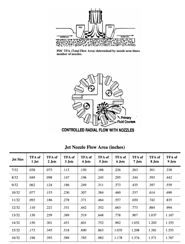
Both roller cone bits and PDC bits have recesses to install different size jet nozzles in order to obtain proper hydraulics. Most roller cone bits use three or four jet nozzles, while PDC bits usually contain six to nine. The flow area of all jets must be determined separately, then added together. For example, suppose four size 9 jets were being used:

There are four jets so the total flow area( TFA ) is 0.0621 x 4 or 0.2486 in2.
Jet nozzles increase the speed of the drilling leaving the bit to around 225 ft/sec, and on many occasions the velocity is much greater. Because nozzle velocity is so important in hydraulic optimization, it should be calculated when the jets are installed in a bit. The formula is:

As mentioned in the previous section, the rate of penetration can be improved if the cuttings are removed from beneath the bit. In soft formations, the hole is generated by the jetting action of the drilling fluid, and the drill rate is limited by connection time, undesirable deviations, and
the loading of the annulus with cuttings. In hard formations, the drill rate
should be proportional to the weight-on-bit, if hole cleaning is adequate.
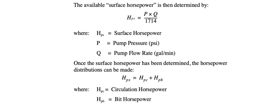
Surface Horsepower
In order to maximize a hydraulics program, all aspects concerning drilling fluids and the associated equipment must be considered.
The first component in any hydraulic design is the surface equipment and the hydraulic horsepower available from them. There are two limiting factors on the surface hydraulic horsepower.
The first is the flow rate range. As discussed earlier, the flow pattern in the annulus should be laminar, therefore the upper limit for the flow rate is a Reynolds Number of 2000. The highest velocity in the annulus will be around the collars, and this velocity can be determined by calculating the “critical velocity” over that section. In addition, running the pumps at that upper range is not always advisable because there will be more wear and tear on the pumps and much more fuel consumption.
The lower limit is a range where there is sufficient hole cleaning. This is determined by using the velocity around the drillpipe and the largest annular section (normally the upper hole section or drillpipe/riser section). A normal range is around 50 ft/min.
The second factor is the operating pressure of the mud pumps. Most mud pumps can produce the required pressure with little problem. However, because of the various components associated with the surface system (standpipe, rotary hose, pulsation dampener, etc.) the maximum surface pressure is usually limited to some value less than the maximum rated pump pressure.

Bottom Hole Horsepower
Determination of the amount of Bottom Hole Cleaning necessary to maximize the drill rate is based upon:
- Hydraulic (Jet) Impact Force
- Hydraulic Horsepower
Maximizing Hpb involves minimizing Hpc, or in other words, the lowest flow rate and the highest pump pressure will result in the highest Hpb. However, the “lowest flow rate” will usually result in inadequate bottom hole cleaning. To compensate for this, bottom hole pressure can be increased by using smaller jet nozzles.
Hydraulic Horsepower
Hydraulic horsepower is based on the theory that cuttings are best removed from beneath the bit by delivering the most power to the bottom of the hole.
The amount of pressure lost at the bit, or bit pressure drop, is essential in determining the hydraulic horsepower. Bit pressure drop is determined by:
MD / (Vn)2 / 1120 = P b
where: MD = Mud Density (lb/gal)
Vn = Nozzle Velocity (ft/sec)
From the bit pressure loss, hydraulic horsepower can be calculated:
Pb /Q / 1714 = H h h
To optimize Bottom Hole Cleaning and Bit Hydraulic Horsepower, it is necessary to select a circulation rate and nozzle sizes which will cause 65% of the pump pressure to be expended forcing the fluid through the jet nozzles of the bit.
Hhh =0.65/Hps
Hydraulic Impact Force
Hydraulic (Jet) Impact Force is based on the theory that cuttings are best removed from beneath the bit when the force of the fluid leaving the jet
nozzles and striking the bottom of the hole is the greatest. Impact Force is determined by:
MD * Q * Vn / 1930 = H i f
where:
MD= Mud Density (lb/gal)
Q = Flow Rate (gal/min)
Vn =Nozzle Velocity (ft/sec)
As can be seen, Impact Force depends on maximizing flow rate and nozzle velocity rather than pressure. Therefore, higher flow rates are required. The emphasis is on a large volume of fluid impacting with moderate force, rather than a small volume impacting at a high pressure.
This condition is optimized when circulating rates and bit nozzle sizes are chosen which will cause 48% of the pump pressure to be used to force fluid through the jet nozzles.
Hif = 0.48*Hps
Fixed Cutter Bit Hydraulics
The hydraulics for fixed cutter bits is based on the drilling fluids ability to remove cuttings beneath the cutters and to cool the bit. Fluid volume is critical to PDC bit performance. Fluid volume and fluid velocity is critical to diamond bit performance.
The major components of fixed cutter bit hydraulics are:
- flow rate – Q (gal/min) and V (ft/min)
- drilling fluid characteristics – MD (lb/gal), YP (lbs/100ft2) and PV (cps)
- pressure loss – across the bit face (diamond bit) or through the jet nozzles (PDC bit)
- the Total Flow Area (TFA) – instead of nozzle sizes
A very important parameter in fixed cutter bits is “Hydraulic Power Per Square Inch” or HSI. It is calculated using Hhp (hydraulic horsepower):
HSI = Hhp /A
where:
Hhp = Hydraulic Horsepower
A = Bit Area (square inches)*
* If the area of the bit is not given, it can be calculated
using:
A = π/4 * d2—
where: d = bit diameter (inches)
The hydraulic horsepower equation is the same (Pb x Q/1714), however in fixed cutter bits, resistance to fluid flow is created by the diamonds, nozzles, flow area restrictions, cuttings and the uneven hole pattern. Pressure losses at the bit are calculated using:
P b = MD * Q2/10858 * TFA2
PDC Bit Hydraulics
Since PDC bits are formation specific (best used in plastic formations), the formation characteristics will determine the hydraulic energy required. The drilling fluid will dictate the HSI, for water-based drilling fluids it will be between 2.5 and 4.5, while for oil-based drilling fluids it will be between 1.5 and 3.0.
The HSI, calculated at the jet nozzle orifices, will have several characteristics which will directly affect hydraulic energy:
- the fluid velocity decreases rapidly once it leaves the nozzles
- high vertical velocity and low horizontal velocities are achieved across the bit face
- for higher volumes of fluid pumped, horizontal velocities will increase, but not necessarily HSI
The increased horizontal velocities provide better cuttings removal, better cooling, and possibly better drill rates.
Nozzle velocity is calculated in the same manner as with rollercone bits.
Diamond Bit Hydraulics
The horizontal fluid velocity is the key element in diamond bit life and bit performance. It can be determined using:
V el = 0.32 * Q / TFA
The fluid courses assist this by directing the drilling fluid across the bit to cool the diamonds and to remove the cuttings.
The diamond bit “Total Flow Area” consists of two components:
- Fluid Course Area – is the area of all fluid courses on the bit. They are cast into the bit body.
- Diamond Exposure Area – is the area between the bit face and formation, produced by the diamond exposure.
The desired TFA is calculated and designed into the bit by varying the diamond exposure, and the width and depth of the fluid courses.
Another phenomenon which occurs with natural diamond bits is called hydraulic pump-off. The hydrodynamic pressure of the mud at the bit acts over the bit face area (between the cutting face of the bit and the formation) and tends to lift the bit off the bottom of the hole. For example, the pump- off force on a 8-1/2 inch radial flow diamond bit (having a pressure drop of 900 psi) would be approximately 8600 pounds. It will require at least this much bit weight to keep the face of the bit in contact with the bottom of the hole.
Diamond Bit Flow Patterns
There are two main flow patterns in diamond bits:
1. Cross Pad Flow System (feeder/collector system)
- a) the fluid travels along the high pressure “primary fluid courses” (those which connect to the crowfoot), to a point where “low pressure collectors” draw the fluid across the diamond pad
- b) this ensures that the diamonds towards the outside diameter are cleaned and cooled
- c) The HSI should be between 1.5 and 2.5.
2. Radial Flow System
a) provides a “high pressure primary fluid course” for each diamond row
b) permits fluid to travel in front of, and behind each diamond pad to facilitate cuttings removal and cooling
c) maintains uniform horizontal fluid velocity by tapering fluid course depth as they approach the outside diameter
d) The HSI should be between 2.0 to 3.0.

Disclaimer: General reading purpose only.